-40%
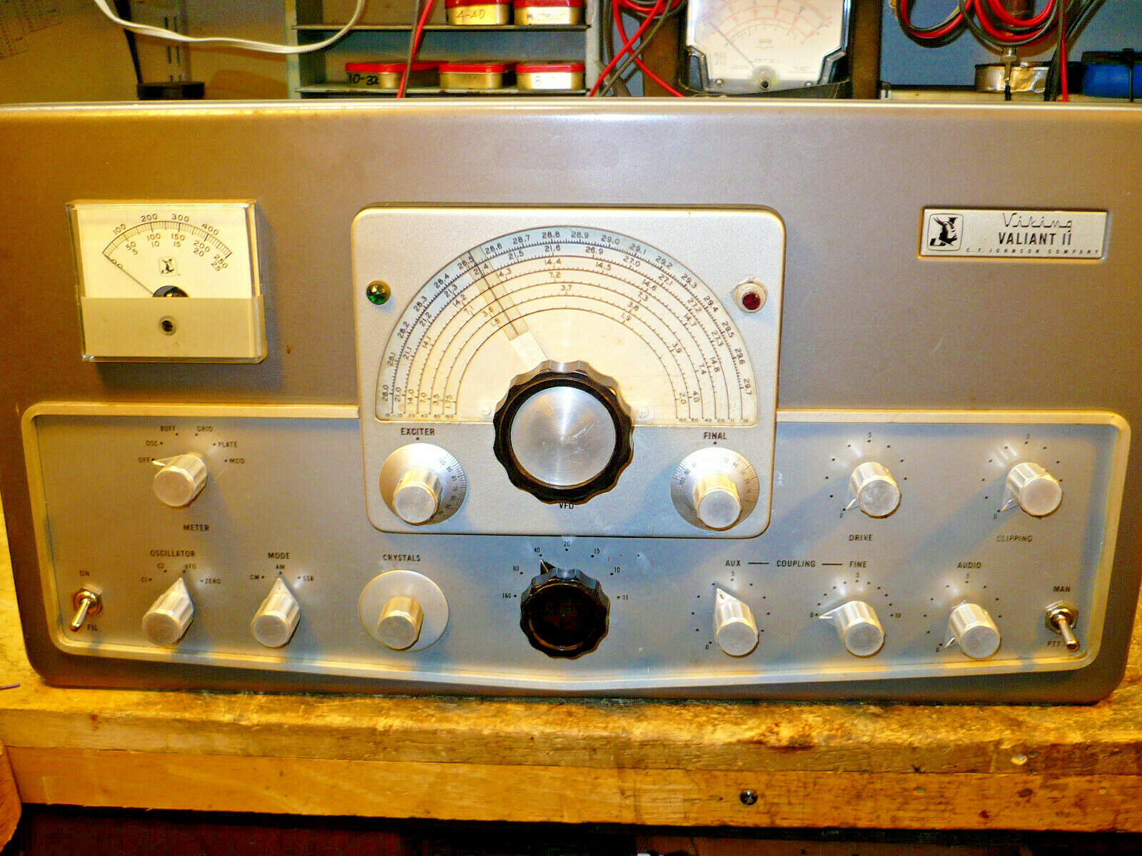
Johnson Valliant II, Rebuild Complete
$ 52.8
- Description
- Size Guide
Description
For AuctionEF Johnson
Viking Valliant II
SN: 8367
Rebuild Complete
* Rebuild Started
* Unit stripped to chassis in preparation for a thorough cleaning
* Unit cleaned, scrubbed, mega-gunk and nicotine removed. Water wash and let air dry for 24 hours before mechanical work begins.
* Mechanical work underway: Tube sockets, terminal strips, rear panel rework ( install MS 8-32 nutplates (20)
* Power transformer output wiring replaced
* Power Transformer end bells repainted
* Power Transformer re-installed.
* LV, Bias & modulator tube socket wiring complete
* Power Transformer wiring complete
* New Power & PTT/Manual switches installed
* Mil grade ceramic modulator tube sockets installed
* Mil grade ceramic PA tube sockets (3) installed
* Jumper socket installed
* Jumper socket heater wiring installed
* PA & Modulator bias wiring reworked and installed
* Fuse Holder for HV transformer installed on rear panel
* New ceramic meter switch installed and wired.
* Microphone and Key Jack installed
* HV rectifier heater wiring installed
* HV rectifier tubes new ceramic mil grade sockets installed
* Under-chassis wiring rebuild approximately 60% complete. RF string rebuild complete
* Tube heater circuit test, all tubes in place
* AC primary circuits wiring completed
* Separate AC Line fuse added for HV transformer
* PTT relay circuit tested
* PA Screen & Grid wiring installed
* Re-mounted R-12
* Microphone input transformer installed
* Fabricated and installed sub-chassis for: +300V regulator, Solid State Drive circuits,Adjustable bias circuits
* Installed and aligned band switch cam and cam striker assembly
* Installed VFO Module
* Bias circuits ( PA & Modulator) circuits tested
* Power supply test points installed: +300VDC regulated, PA & Modulator Bias
* +300VDC regulator circuit tested
* Solid State Drive Control circuit tested
* NOTE: Microphone Audio Clipper Circuit has been removed (bypassed, all components except tube socket have been removed). Panel control left in place but non-functional.
* VFO output switching circuits test
* Microphone input, PTT and Keying circuits connected to their appropriate rear panel connectors.
* Keying circuit testing
* Modulator tubes anode cap assemblies installed
* PA Tubes Bias level checked at PA tube grids.
* Modulator tubes bias level checked at Modulator tube grids.
* Installed temporary panel meter
* Oscillator, Buffer, Grid metering tested all bands (VFO Input, CW Mode)
* Installed VFO shroud
* Enlarged VFO coupler access chassis opening
* Re-check +300VDC regulator under load conditions.
* Install Plate Choke and HV bypass capacitors
* Re-check bias circuits under load conditions
* Adjusted Keyer circuit: tested CW & AM keyer operation.
* Microphone preamplifier circuit tested to grids of modulator tubes.
* Soldered RF Connections around PA Tank coil: Note: In addition to secure mechanical connections, we solder all RF connections. The only non-soldered RF circuit connections are the PA Tube anode cap connector assemblies.
* Install top-of-chassis shield assembly
* Fabricate, install and test neon "transmit" lamp assembly.
* Installed SSB input connectors and cables.
* Fabricated (3) clamp-on PA Anode connectors
* Installed partial PA plate connections ( silver plated brass)
* Installed Sprague 30KV plate blocking capacitor
* Install 40 meter PA tuning shunt capacitors ( 150pf total). We use HV doorknob capacitors.
* Installed HV Power transformer
* Installed HV Filter Choke
* Installed HV Filter Capacitor/Bleeder assembly
* Tested HV circuit ( No load). Test satisfactory. Bleeder circuit test satisfactory
* Installed front panel
* Cleaned & repainted meter rear cover, replaced panel meter filter components
* Panel meter re-connected
* Control knobs cleaned, new allen set screws installed, knobs installed
* Sub-panel edge gasket replaced
* New "Transmit" indicator lamp holder installed ( Red Cap)
* Tested Panel meter
* Installed ball drive snubber assembly
* Installed front sub-panel
* Replaced front sub-panel edge gasket
* Installed VFO dial and VFO tuning knob
* Installed Buffer and PA tuning knobs
* Fabricated and installed new (3) PA Suppressor assemblies
* Installed all loading fixed capacitors
* Adjusted PA Clamp circuit per manual
* Adjusted Modulator Idle IP per manual.
* Installed new 30KV 500pf plate blocking capacitor
* Installed new PA Tuning Shunt Capacitors
* Final testing complete
* Modulation envelope test complete
* Cabinet included.
* This is the last remaining Valiant that we have rebuilt.
* Want to reserve this unit ? follow the links below for more information.
* All Sales Final, No Warranties expressed or implied. No returns. Technical assistance if necessary via Email.
* This transmitter does NOT have a functioning 11 meters, so don't ask.
* Local Pickup Only.( We do not fabricate shipping containers).. Feel Free to make your own shipping arrangements.
Tubes removed and packaged separately. Gross weight ) approximately 100#.
Our direct email links are here:
http://members.ebay.com/ws/eBayISAPI.dll?ViewUserPage&userid=cornelius_connie
www.kiss-electronics.com
